Month: November 2021

Mapware’s Photogrammetry Pipeline, Part 2 of 6: Homography

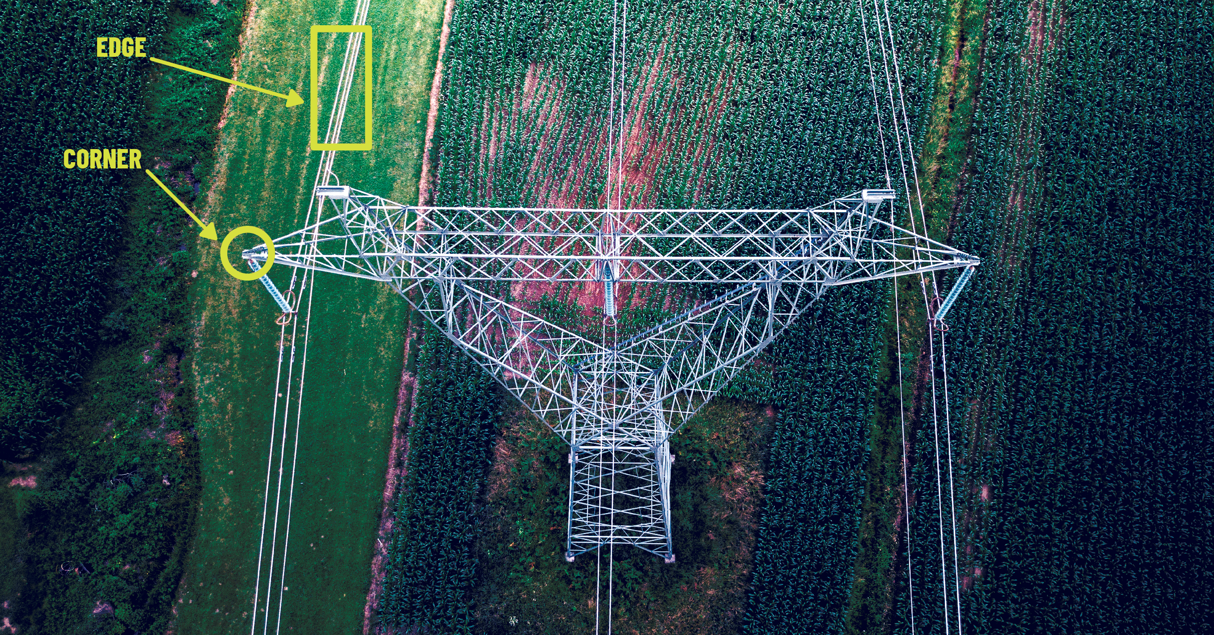
In the previous article on Mapware’s photogrammetry pipeline, we described how our software uses keypoint extraction to help a computer see the most distinctive features in each image without human eyes.

The next step, homography, involves pairing images together based on their keypoints. To understand how this works, you need to know a little more about how a computer “sees” images.

The limits of computer vision

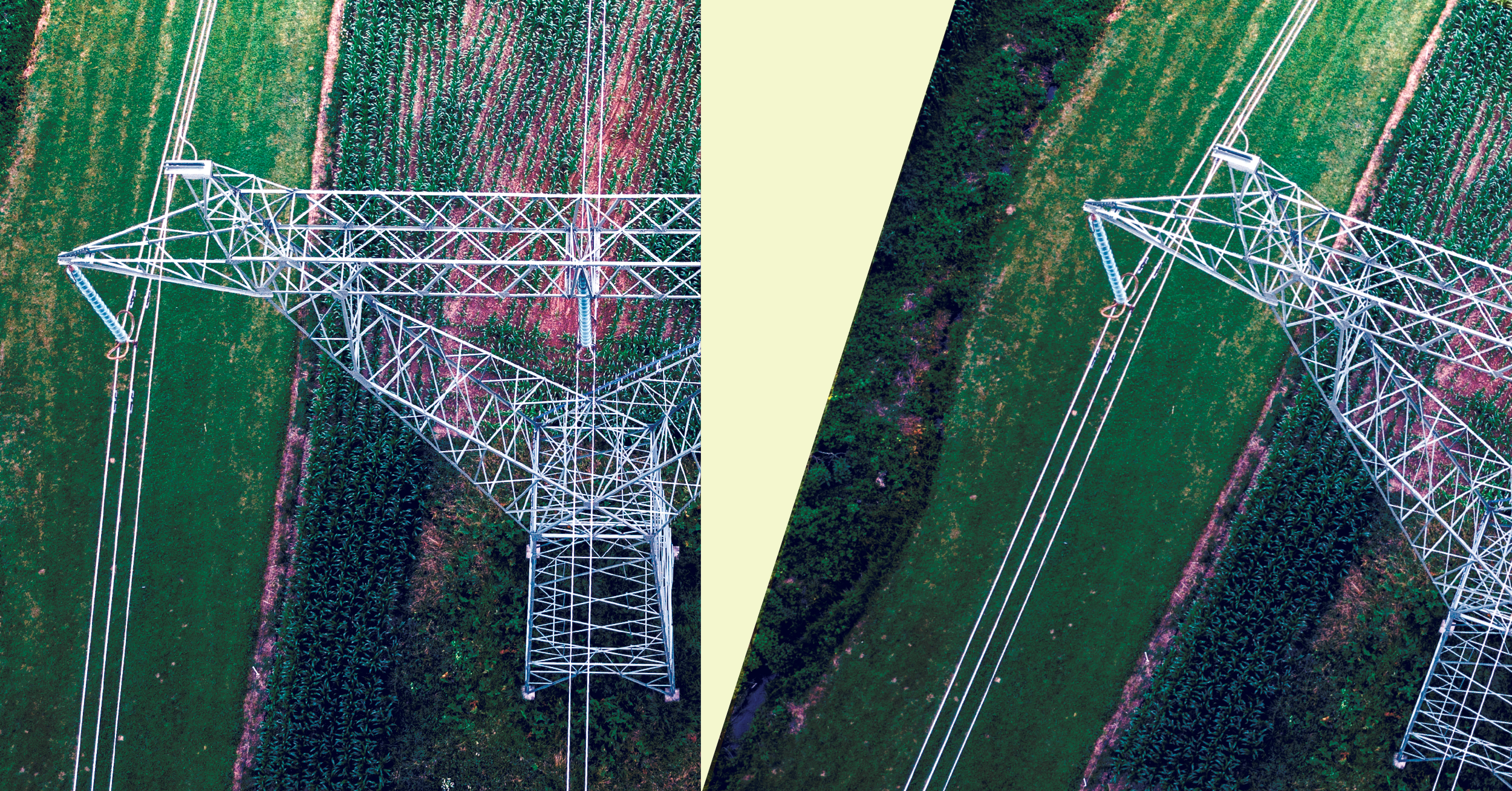
It can be helpful to think of photogrammetry image sets like puzzle pieces. In the same way that humans snap puzzle pieces together into a complete picture, photogrammetry software connects drone images together to generate a 3D model of the whole site.

But there’s an important difference. Unlike humans, computers don’t actually understand the features depicted in each image. Whereas a human might intuitively know that a puzzle piece showing the back half of a truck connects to another piece showing its front half, a computer wouldn’t know that they go together because it doesn’t see a truck – it sees pixels.

Figure 1: A human sees the bright-red corner of a truck over a blue highway. Mapware’s algorithm detects a rapid change in grayscale intensity values between pixels.

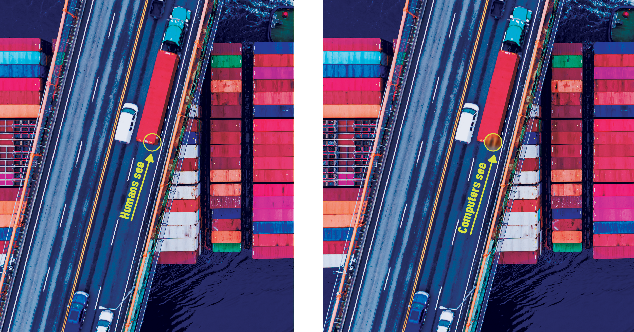
What a computer can do, however, is identify the same truck in two images based on their mathematically similar keypoints. This is why drone photographers take overlapping photos.

The purpose of overlap

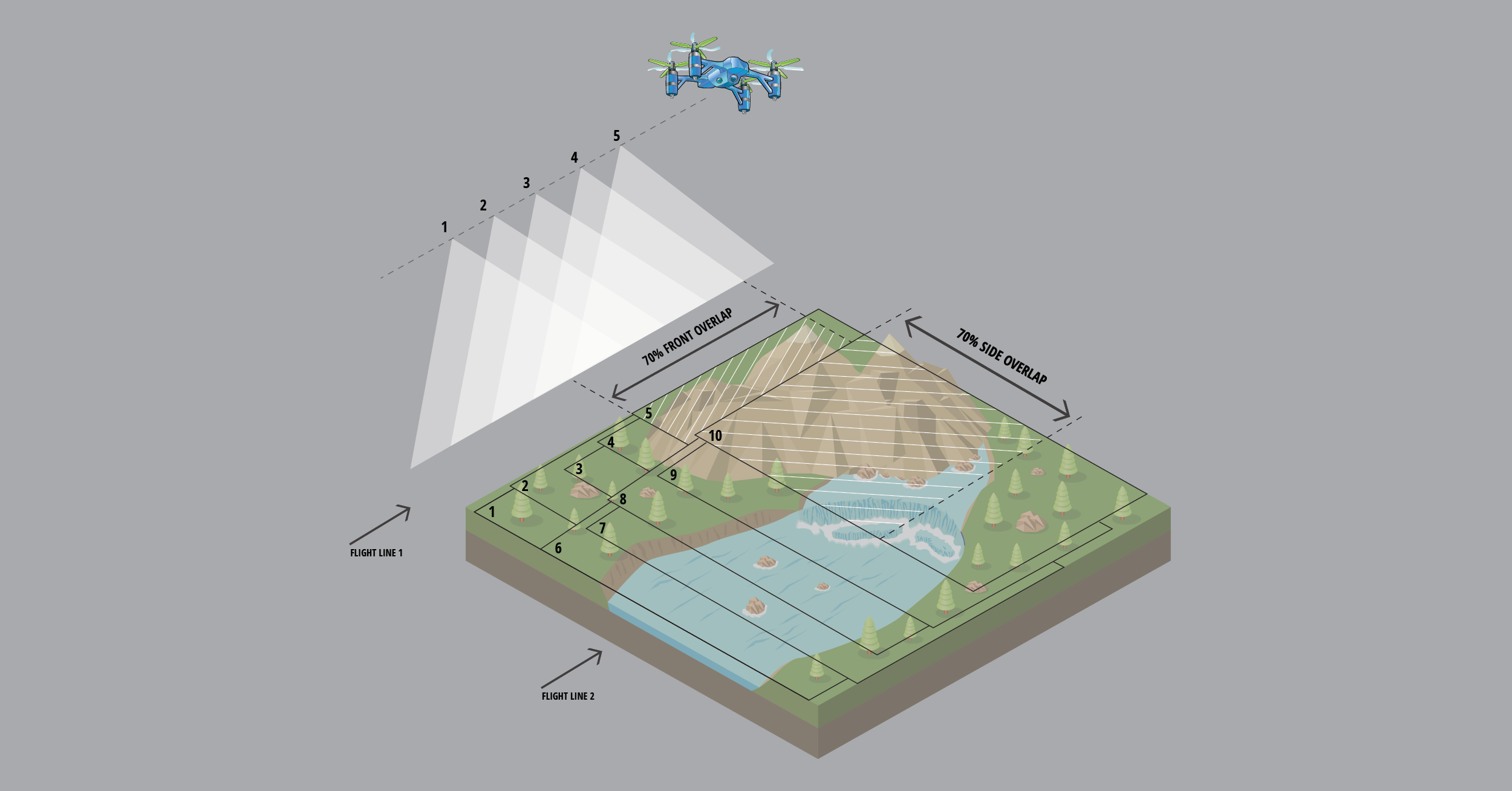
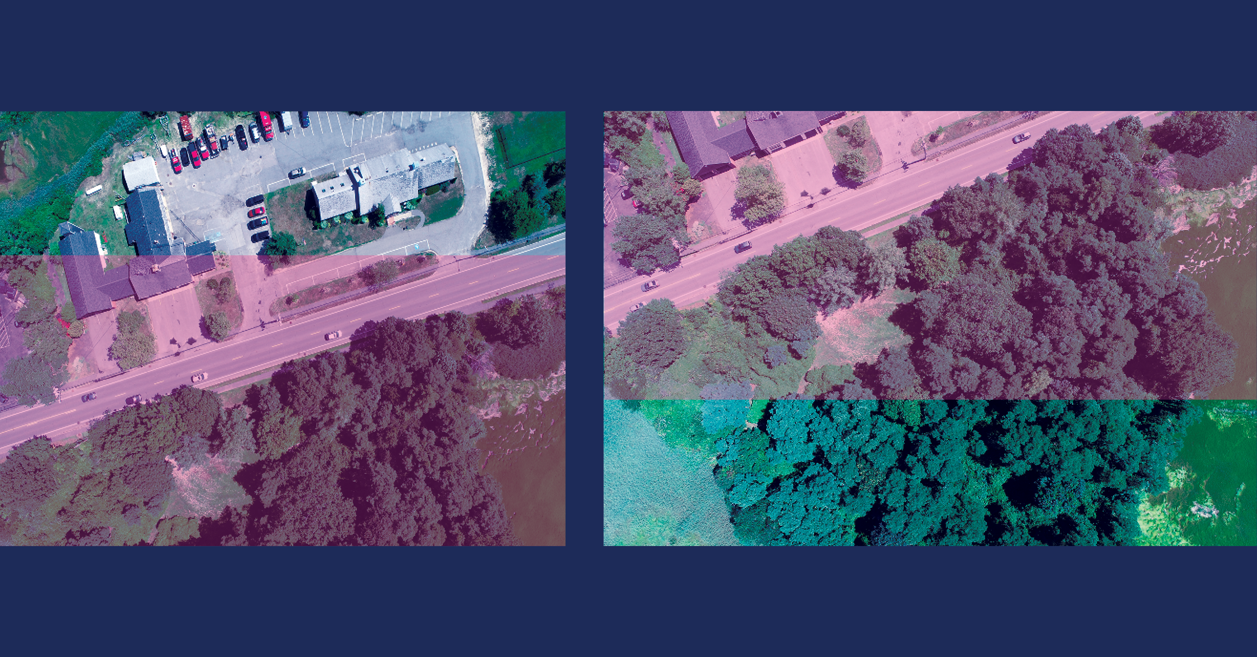
Overlap occurs when two adjacent photographs show part of the same scene on the ground. If you take two photos with 50% overlap using a drone, that means you take the second photo when the drone has only moved halfway beyond the area where it took the first photo. Any keypoints generated within the overlapping region are created twice—one per image. The similarities between these keypoints will help the computer pair photos go together during homography.

NOTE: Many drone flight control apps are designed to automate photogrammetry data capture, and these typically let pilots specify the amount of overlap they want between adjacent images. If you are using one of these, Mapware recommends configuring a front and side overlap of 70% to generate the highest quality models.

Figure 2: We recommend taking photos that overlap one another by 70%, both from the front and sides. This increases the odds that two or more photos will display the same feature and Mapware will match their keypoints.

The homography process (in two steps)

In the homography process, Mapware considers each pair of images independently (pair by pair) to identify which images overlap and, if so, what is the best possible linear transformation that relates the first image to the second image. In other words, for a given point in the first image, Mapware determines how to transform it to get the corresponding point in the second image. We’ll break this two-step process down below.

Step 1: keypoint matching

In the first step, Mapware runs an algorithm to compare each image in the set to every other image in the set. If it finds two images with nearly identical keypoint fingerprints, it designates the two images as a pair. Mapware iterates through the entire image set until each image is (hopefully) paired with at least one other image.

Figure 3: Mapware employee Dan Chu took these two photos while flying a DJI Inspire 2 over Sandwich, Massachusetts as part of Operation Bird’s Eye. The photos share a large overlapping region (highlighted above in pink). Mapware looks for similar keypoints in that region to pair these images.

Step 2: linear transformation

Remember that keypoint fingerprints are invariant (unchanging) with regards to scale and orientation – meaning they generate nearly identical values even after being enlarged, shrunk, or spun around. This is important in the keypoint matching step because it helps Mapware pair two images even if one image is taken by a drone at a higher altitude or different angle.

But Mapware must eventually stitch all of the images together into a 3D model, and that involves undoing these differences to help the images fit together properly. The second step of the homography process does this using linear algebra. It finds the most probable linear transformation between the two keypoints—in other words, it mathematically calculates the best way to stretch, rotate, and translate the first image’s keypoints so they are identical to the second image’s keypoints.

After homography

Once Mapware has identified image pairs and calculated their scale/orientation differences, it can align all the images together into a composite image of the whole landscape. This is called structure from motion (SfM) and will be described in the next article in this series.

Mapware’s Photogrammetry Pipeline, Part 1 of 6: Keypoint Extraction

Mapware can create a 3D digital twin of a landscape from a set of 2D aerial photos. In this article, we discuss the first step in Mapware’s photogrammetry pipeline: keypoint extraction.

Purpose of keypoint extraction

When users upload digital images to Mapware and initiate its photogrammetry process, the first step is keypoint extraction: identifying the distinctive features in each image and assigning them values that a computer can easily reference later.

Keypoint extraction begins the photogrammetry pipeline for two reasons.

First, it assists with computer vision, the science of helping a computer understand an image the way humans do by picking out the most interesting shapes from the background. This helps Mapware later in the pipeline when it stitches image sets together into a 3D digital twin.

More importantly, keypoint extraction aids in image compression. Typical photogrammetry projects can require hundreds or even thousands of photos, with each photo containing millions of pixels. Reading these large image sets can be memory-intensive, increasing the risk of system crashes. But keypoints serve as bookmarks in each image file, allowing computers to read the important features and ignore the rest. The result is faster and more-reliable processing.

The keypoint extraction process

Mapware identifies keypoints like most photogrammetry software, using a combination of corner detection, descriptor assignment, and invariance calculation.

  • Corner Detection: To identify distinctive features in each photo, Mapware’s corner detection algorithms search for pixel groups whose grayscale intensity values differ substantially from their neighbors. These can either be edges—boundary lines between two areas of differing intensity—or corners—points where two lines converge. Mapware identifies edges and corners, but only designates corners as keypoints. This is because corners are easier to localize using cartesian (x, y) coordinates, whereas edges could be lines that run the entire length of an image. You might think of corner detection as loosely similar to the way human eyes notice highly-contrasting features in an image. However, the comparison is arbitrary, as computers may not notice the same image features a human would.
Figure 1: Mapware ignores edges and generates keypoints from corners, because corners are easier to pinpoint in an image.
  • Fingerprint Assignment: To aid in image compression, Mapware then runs another algorithm to mathematically reduce each keypoint into a compact hash called a fingerprint. Some other photogrammetry products refer to these as “descriptors” because they not only help a computer quickly find a keypoint later in the image, but also describe its properties. Thanks to fingerprint assignments, Mapware doesn’t have to process entire images again; it can just read their (smaller) fingerprints.
  • Invariance Calculation: To help stitch photos together later in the photogrammetry pipeline, Mapware ensures each fingerprint is invariant (unchanging) with respect to scale and orientation. In real-world terms, this means a pilot can photograph the same feature twice from different heights and angles—and Mapware will assign nearly identical fingerprints to both images despite their differences. This helps Mapware match photos of the same feature in spite of the changing flight paths of a camera drone.
Figure 2: Thanks to the invariance built into the fingerprint algorithm, Mapware recognizes the same feature in these images even though they were taken from different angles and heights.

How Mapware uses keypoints

After Mapware has identified the keypoints in each image and assigned their fingerprints, it can gradually assemble individual images together into the composite that will become a 3D digital twin.

It starts by identifying pairs of images that have nearly identical keypoints. These keypoint pairs exist because drone pilots take photos with overlap to ensure that the same features will appear on more than one image. For example, they may ensure the same feature appearing at the back of one photo appears at the front of the next photo.

If Mapware identifies the same keypoint in both images, it knows to pair them together on their overlapping region. The next article in this series describes the keypoint pairing step, which is called homography.