The Aerial Perspective Blog
Mapware’s Photogrammetry Pipeline, Part 2 of 6: Homography
In the previous article on Mapware’s photogrammetry pipeline, we described how our software uses keypoint extraction to help a computer see the most distinctive features in each image without human eyes.
The next step, homography, involves pairing images together based on their keypoints. To understand how this works, you need to know a little more about how a computer “sees” images.
The limits of computer vision
It can be helpful to think of photogrammetry image sets like puzzle pieces. In the same way that humans snap puzzle pieces together into a complete picture, photogrammetry software connects drone images together to generate a 3D model of the whole site.
But there’s an important difference. Unlike humans, computers don’t actually understand the features depicted in each image. Whereas a human might intuitively know that a puzzle piece showing the back half of a truck connects to another piece showing its front half, a computer wouldn’t know that they go together because it doesn’t see a truck – it sees pixels.
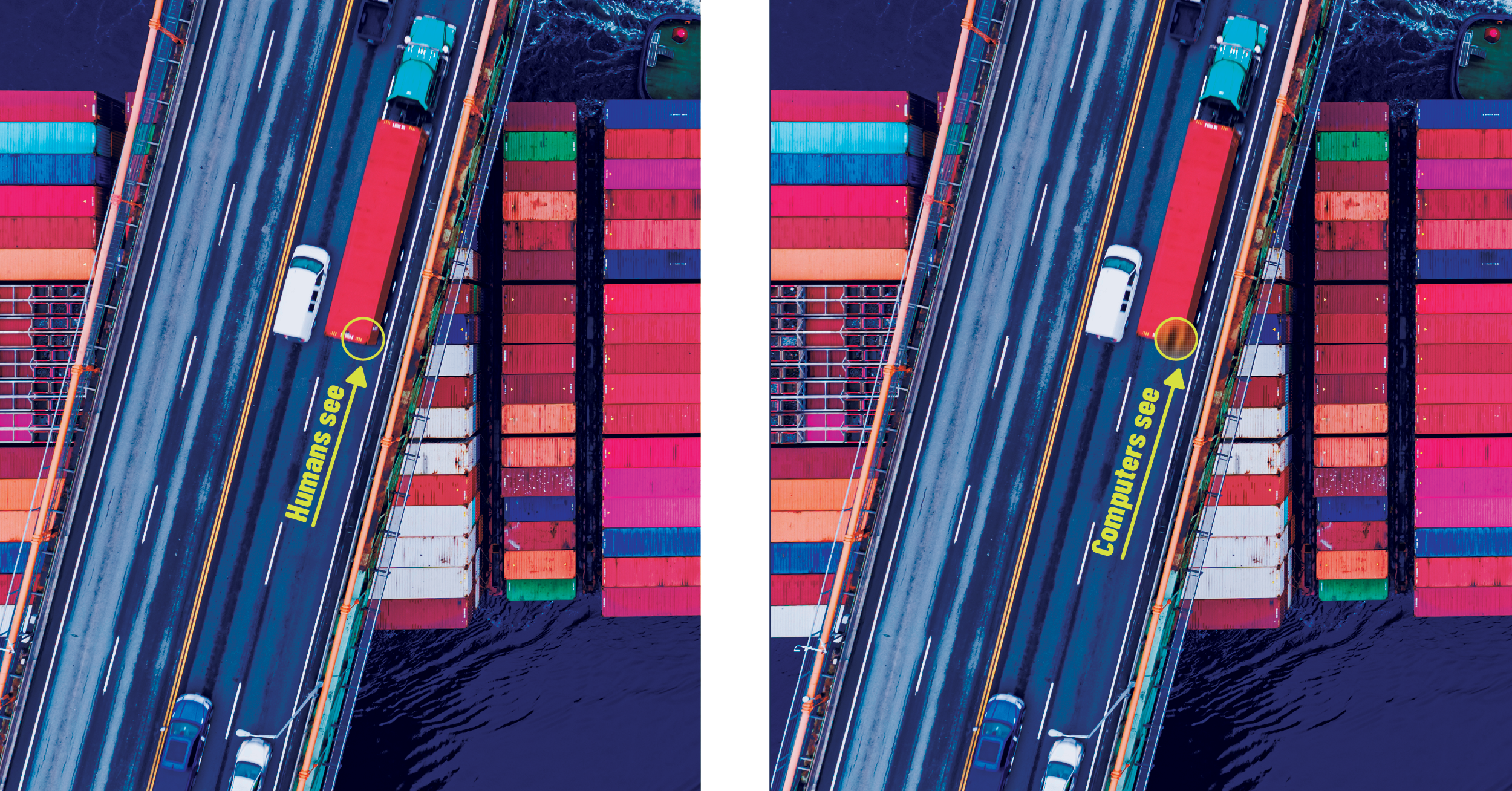
What a computer can do, however, is identify the same truck in two images based on their mathematically similar keypoints. This is why drone photographers take overlapping photos.
The purpose of overlap
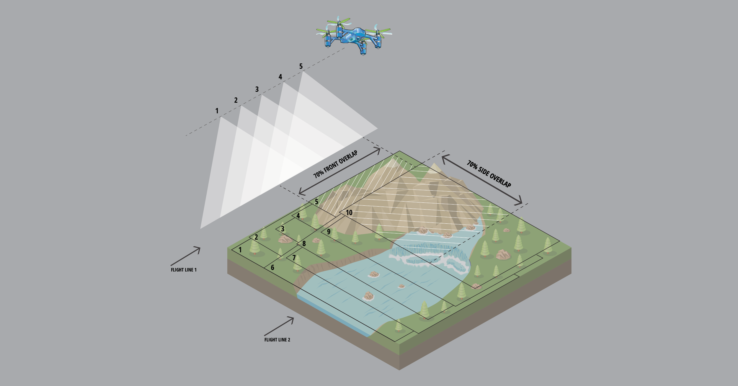
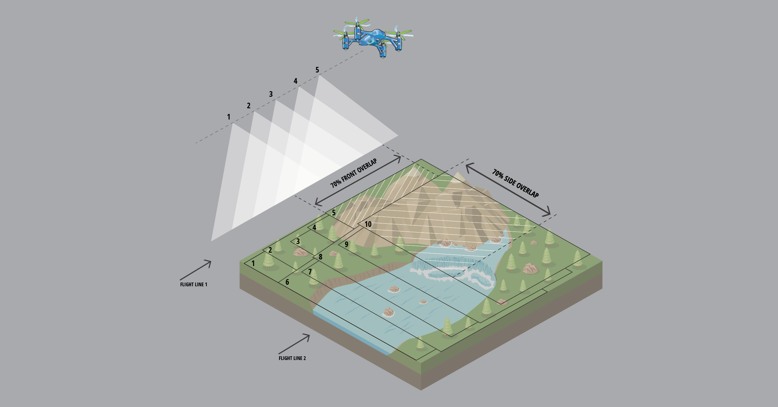
Overlap occurs when two adjacent photographs show part of the same scene on the ground. If you take two photos with 50% overlap using a drone, that means you take the second photo when the drone has only moved halfway beyond the area where it took the first photo. Any keypoints generated within the overlapping region are created twice—one per image. The similarities between these keypoints will help the computer pair photos go together during homography.
NOTE: Many drone flight control apps are designed to automate photogrammetry data capture, and these typically let pilots specify the amount of overlap they want between adjacent images. If you are using one of these, Mapware recommends configuring a front and side overlap of 70% to generate the highest quality models.
The homography process (in two steps)
In the homography process, Mapware considers each pair of images independently (pair by pair) to identify which images overlap and, if so, what is the best possible linear transformation that relates the first image to the second image. In other words, for a given point in the first image, Mapware determines how to transform it to get the corresponding point in the second image. We’ll break this two-step process down below.
Step 1: keypoint matching
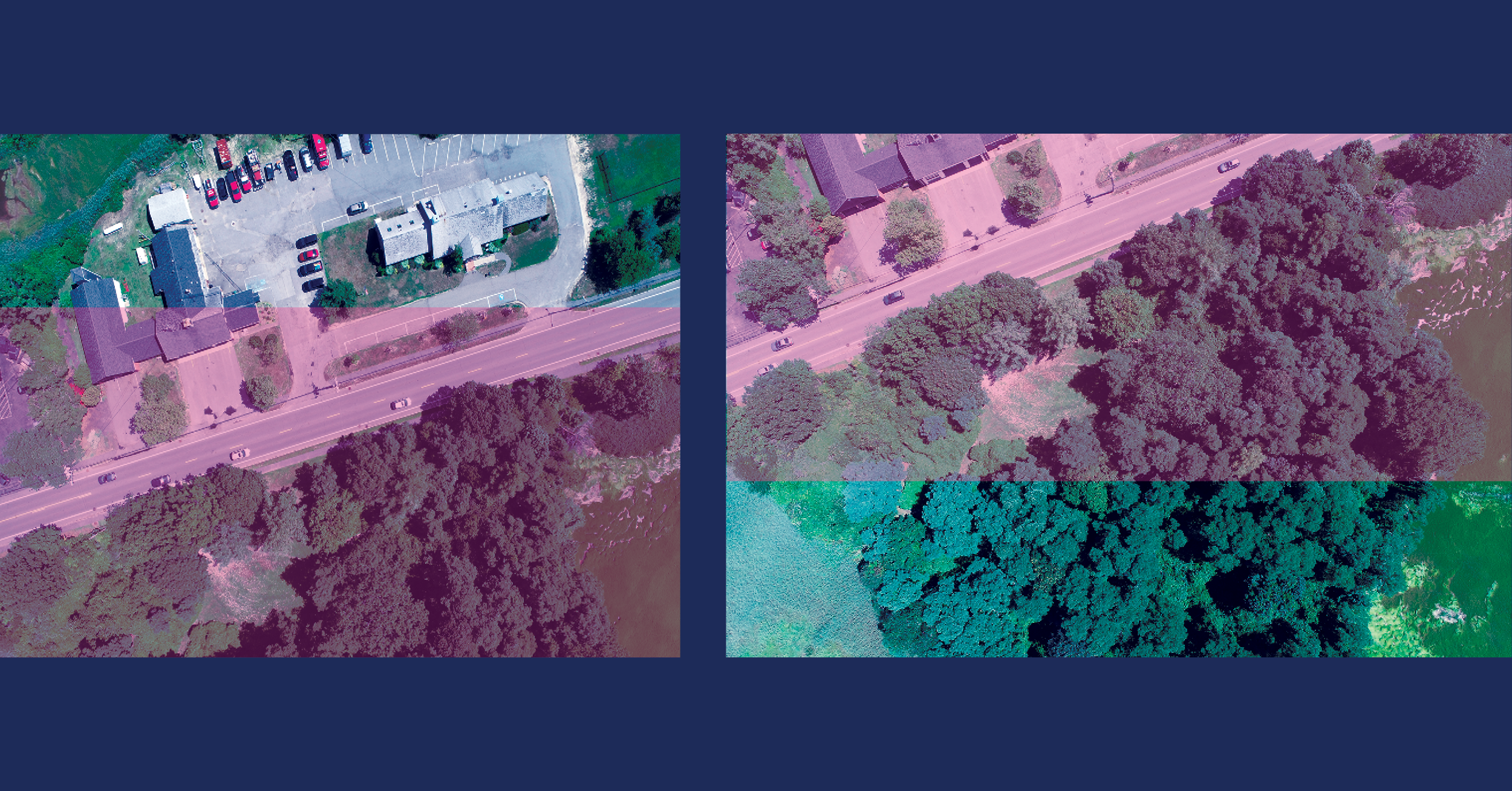
In the first step, Mapware runs an algorithm to compare each image in the set to every other image in the set. If it finds two images with nearly identical keypoint fingerprints, it designates the two images as a pair. Mapware iterates through the entire image set until each image is (hopefully) paired with at least one other image.
Step 2: linear transformation
Remember that keypoint fingerprints are invariant (unchanging) with regards to scale and orientation – meaning they generate nearly identical values even after being enlarged, shrunk, or spun around. This is important in the keypoint matching step because it helps Mapware pair two images even if one image is taken by a drone at a higher altitude or different angle.
But Mapware must eventually stitch all of the images together into a 3D model, and that involves undoing these differences to help the images fit together properly. The second step of the homography process does this using linear algebra. It finds the most probable linear transformation between the two keypoints—in other words, it mathematically calculates the best way to stretch, rotate, and translate the first image’s keypoints so they are identical to the second image’s keypoints.
After homography
Once Mapware has identified image pairs and calculated their scale/orientation differences, it can align all the images together into a composite image of the whole landscape. This is called structure from motion (SfM) and will be described in the next article in this series.
Join our mailing list to stay up to date on the latest releases, product features and industry trends.
Mapware needs the contact information you provide to us to contact you about our products and services. You may unsubscribe from these communications at any time. For information on how to unsubscribe, as well as our privacy practices and commitment to protecting your privacy, please review our Privacy Policy.
